Introduction: Why Tank Jacking Matters
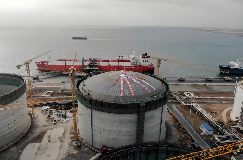
Imagine a 50-meter diameter, 5,000-ton crude oil storage tank, full of product, that requires critical repairs to its deteriorating foundation. The traditional approach—emptying, dismantling, and rebuilding—is a monumentally expensive, time-consuming, and disruptive nightmare. This is where the engineering marvel of Tank Jacking comes in.
Tank jacking is a highly specialized engineering technique that uses computer-controlled hydraulic synchronization system to lift or lower massive storage tanks—often while they remain in service—in a controlled and precise manner. It is the cornerstone of modern tank maintenance, modification, and relocation projects, offering unparalleled efficiency and safety over traditional methods.
This ultimate guide delves into the fundamentals, applications, equipment, and meticulous procedures that define a successful tank jacking project, providing a comprehensive resource for engineers, project managers, and industry professionals.
Chapter 1: Understanding the Fundamentals of Tank Jacking
1.1 What is Tank Jacking?
At its core, tank jacking is the controlled elevation or descent of a storage tank using an array of hydraulic jacks operating in perfect unison. The system is designed to distribute the immense structural load evenly around the tank’s circumference, preventing localized stress, deformation, or collapse. The key advantages are:
- Cost Savings: Drastically reduces downtime and avoids the costs of complete dismantling.
- Time Efficiency: Projects can be completed in days or weeks instead of months.
- Enhanced Safety: Minimizes hot work and confined space entry; the process is controlled from a safe distance.
- Minimal Disruption: Tanks can often be lifted with product inside (“product-on” jacking), avoiding costly transfer and cleaning.
1.2 Key Principles Behind the Technology
The success of jacking hinges on three fundamental engineering principles:
- Load Distribution: The weight of the tank (shell, roof, and product) is transferred through strategically placed jacks onto a system of load distribution beams and mats, which spread the force safely to the ground or new foundation.
- Synchronous Lifting: This is non-negotiable. Even a few millimeters of differential lift between jacks can induce catastrophic stress in the tank shell. A computer-controlled system continuously monitors and adjusts each jack to maintain perfect synchrony.
- Stability & Balance: Engineers must calculate the tank’s center of gravity, considering product levels and internal structures. The jacking system must counteract external forces like wind load throughout the operation.
Chapter 2: Primary Applications of Tank Jacking
Tank jacking is not a one-trick pony; it serves a multitude of critical purposes:
- Tank Foundation Repair and Replacement: The most common application. Lifting the tank provides full access to repair corroded concrete ringwalls, replace eroded tank bottom plates, and install new insulation or cathodic protection anodes.
- Elevation Adjustment and Debottlenecking: Raising a tank creates space underneath for new piping, nozzles, or pumps to improve process flow (“debottlenecking”). It can also ensure sufficient gravity head for feeding downstream units.
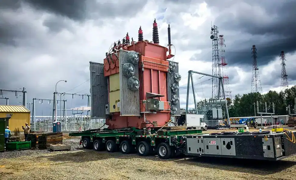
- Tank Relocation and Translation: Jacking is the first step in moving a tank. Once elevated, it can be placed onto multi-directional skidders or trailers to be moved to a new location within a facility or even to a different site entirely.
- New Construction and Installation: For large, field-erected tanks, jacking systems can be used to precisely lower a newly constructed roof onto the shell or to lift the entire tank for final alignment and grouting of the foundation.
Chapter 3: The Tank Jacking System: Components and Equipment
A typical system is comprised of four main subsystems:
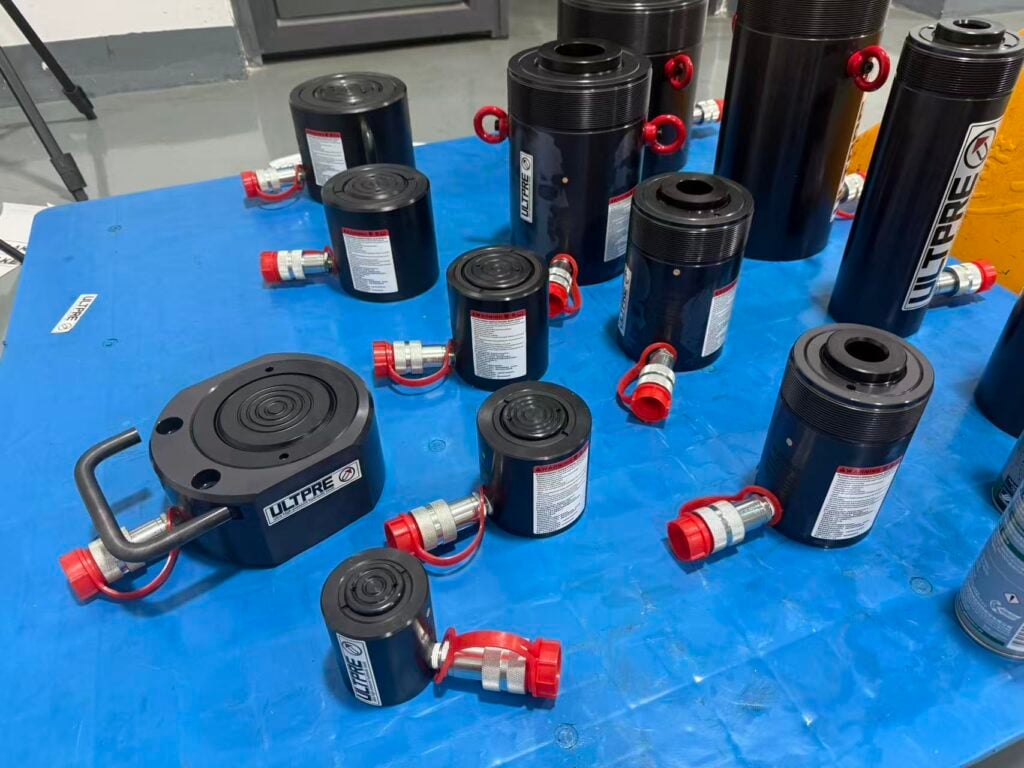
- 3.1 Hydraulic Jacks: The workhorses. High-capacity (often 100-500 metric ton) hollow plunger jacks are preferred as they allow for the insertion of a threaded bar for a secondary mechanical safety lock. They feature built-in safety check valves to prevent accidental lowering.
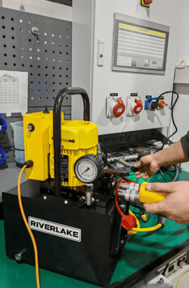
- 3.2 Power Pack Unit (PPU): The heart of the system. This diesel or electric-powered unit generates the high-pressure hydraulic fluid flow required to actuate all jacks simultaneously.
- 3.3 Synchronous Lifting Control System: The brain. A programmable logic controller (PLC) receives real-time data from a displacement sensor on each jack. The system automatically adjusts hydraulic flow to each jack to maintain a pre-set lifting level, typically with an accuracy of ±1.0 mm. All data is displayed on a human-machine interface (HMI) for operator monitoring.
- 3.4 Lifting Frame and Accessories:
- Lifting Lugs / Cradles: Specially designed clamps that attach to the tank’s upper shell wall, providing a secure point for the jack to apply force.
- Load Distribution Beams: Robust steel beams that sit under the jacks to spread the point load over a larger area of the temporary foundation or ground.
- Shims/Packing Plates: Used to take up space and provide support during the incremental lifting process.
- Temporary Support Props: Once lifted to a certain height, sturdy steel props are installed to provide mechanical safety backup.
Chapter 4: The Step-by-Step Tank Jacking Procedure
Phase 1: Pre-Jacking Engineering & Planning (The Most Critical Phase)
- Site Survey: Precise measurements of tank diameter, height, weight (empty and full), and foundation condition.
- Engineering Calculations: Finite Element Analysis (FEA) may be used to determine the optimal number and location of jacking points to avoid shell buckling. Load calculations verify ground bearing capacity.
- Documentation: A detailed Method Statement, Job Safety Analysis (JSA), and Emergency Response Plan are developed and approved.
Phase 2: Site Preparation & Setup
- The tank is taken out of service, cleaned, and gas-freed (if required for the work scope). For “product-on” lifts, precise weight calculations are essential.
- All connected piping and electrical conduits are disconnected.
- The work area is secured, and the ground is prepared for the jacking equipment.
- Jacks, load beams, and control systems are installed and calibrated. A full system test is performed without load.
Phase 3: The Lifting Sequence
- Initial Trial Lift (10-20 mm): The tank is lifted just clear of its foundation. The system is held under load for a period while engineers check for any pressure drops, system anomalies, or unexpected structural behavior.
- Incremental Lifting: If the trial lift is successful, lifting continues in small, controlled increments (e.g., 50-100 mm per step). After each step, temporary supports are installed, and the system is re-checked.
- Real-Time Monitoring: Engineers continuously monitor sync levels, hydraulic pressure, and tank levelness from the control station.
Phase 4: Holding, Work Execution, and Lowering
- Upon reaching the target height, the tank is securely placed on temporary support towers.
- The planned work (e.g., concrete demolition and repouring) is executed.
- Once work is complete and the new foundation has cured, the synchronized lowering process begins, essentially the lifting sequence in reverse.
- The tank is finally seated onto its new foundation, re-connected, and commissioned.
Chapter 5: Critical Safety Considerations and Best Practices
5.1 Common Risks: Structural failure, equipment malfunction (e.g., hose burst), loss of sync, ground failure, and personnel injury from falling objects or pinch points.
5.2 Essential Safety Protocols:
- Competence: Only trained and certified personnel should operate the equipment.
- Redundancy: The system must have multiple safety layers: mechanical locks on jacks, secondary safety valves, and manual override capabilities on the control system.
- Exclusion Zones: Strict barricading to prevent entry under the lifted load at all times.
- Communication: Clear radio communication protocols between the control operator and all field technicians.
5.3 Best Practices:
- Never exceed the rated capacity of any component in the system.
- Always assume the tank is heavier than calculated; build in a conservative safety factor.
- Monitor weather forecasts closely; operations must pause in high winds or lightning.
- Meticulous documentation of every lift step, pressure reading, and inspection is paramount.
Chapter 6: Advanced Techniques and Future Trends
The field is evolving with innovations like:
- Optical Monitoring Systems: Using 3D laser scanning to create a real-time digital twin of the tank during lift, detecting deformation far more precisely than traditional methods.
- Integrated Skidding Systems: Combining jacking and skidding systems for seamless lifting and translation in a single contract.
- Enhanced Data Analytics: Using historical lift data to predict system performance and optimize future projects.
Conclusion
Tank jacking is a powerful, sophisticated solution that transforms what was once an insurmountable challenge into a manageable, routine operation. Its success is not a matter of brute force but of precision engineering, meticulous planning, and unwavering adherence to safety protocols. By understanding the principles and procedures outlined in this guide, project teams can confidently leverage this technology to execute complex tank projects with unparalleled efficiency and safety.
Remember, the most critical component in any jacking operation is not the hydraulic jack itself, but the experienced and reputable engineering team that designs and manages the process from start to finish.