Introduction: The Critical Role of Controlled Force
When technicians at a German wind farm attempted to remove a 1.2-ton gearbox bearing using sledgehammers, the resulting shaft damage caused €58,000 in repairs and three weeks of downtime. This preventable disaster underscores why professional pullers are non-negotiable in modern maintenance. Pullers deliver controlled extraction force to separate interference-fit components—from delicate bearings to massive turbine couplings—without damaging expensive assets.
What is a Puller? Engineering Principles
A puller is a force-multiplying mechanical device designed to disassemble tightly fitted components through controlled tension. Unlike impact tools that deliver shock loads, pullers apply gradual, measurable force along the component’s central axis.
Core Components:
- Force Arms: Forged from 42CrMo alloy steel (tensile strength ≥1,100 MPa)
- Center Mechanism: Precision ACME trapezoidal threads (Grade 8G) for force amplification
- Gripping Jaws: Heat-treated claws with reversible configurations (external/internal)
The Physics of Extraction:
F(required)=μ⋅P⋅A
Where:
- μ = Coefficient of friction (0.12–0.18 for steel/steel)
- P = Contact pressure from interference fit (MPa)
- A = Contact surface area (mm²)
For example: Removing a 100mm diameter bearing with 0.05mm interference requires ≈37kN force—equivalent to lifting a 3.7-ton vehicle.
Primary Industrial Applications
| Industry | Critical Use Case | Damage Risk Without Puller |
|---|---|---|
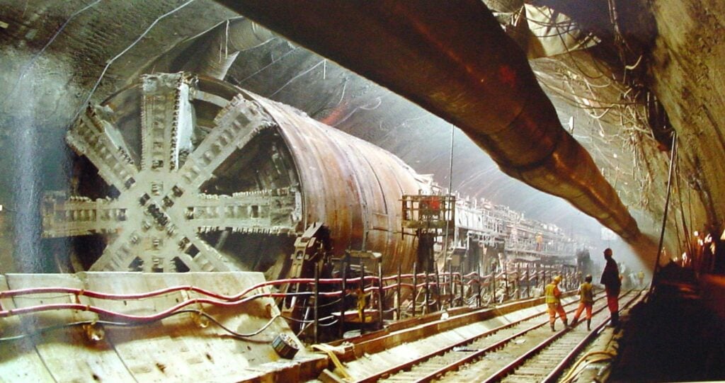
| Wind Energy | Generator coupling removal | Bent shafts (>€100k repair) |
| Rail Transport | Wheelset bearing extraction | Journal scoring (Ra>3.2μm) |
| Aerospace | Turbine disk disassembly | Cracking in Ti-6Al-4V alloys |
| Automotive | Transmission gear removal | Tooth deformation (>0.1mm runout) |
Puller Types: Capabilities & Limitations
Mechanical Pullers
| Type | Max Capacity | Ideal For | Critical Limitation |
|---|---|---|---|
| 3-Jaw Pullers | 200 kN | General-purpose disassembly | Arm slippage on tapered surfaces |
| Slide Hammers | 50 kN | Light-duty field repairs | Poor force control (±25%) |
| Gear Pullers | 350 kN | Sprocket removal | Minimum 80mm clearance required |
Hydraulic Pullers
| Type | Force Range | Precision | Game-Changing Feature |
|---|---|---|---|
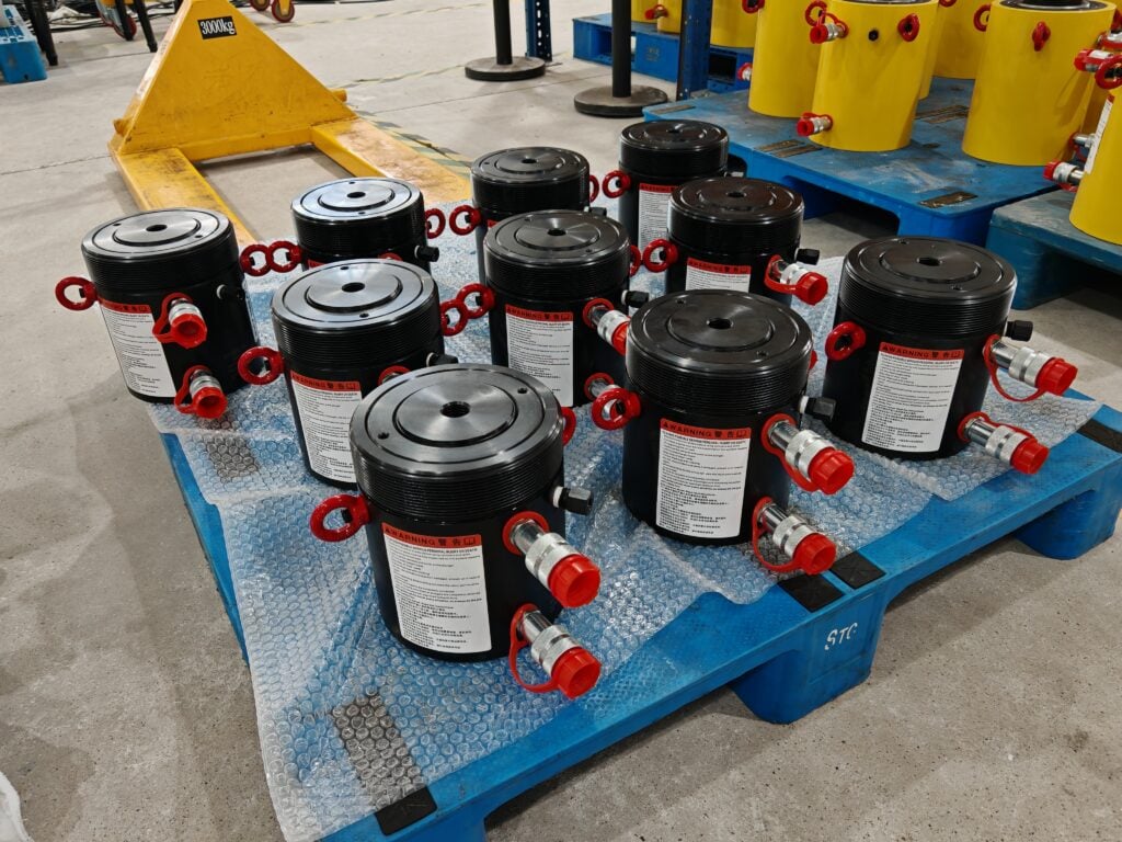
| Cylindrical | 50–1,000 kN | ±0.02mm displacement | Real-time pressure monitoring |
| Split-Frame | 200–2,000 kN | Self-centering (±1°) | No shaft disassembly needed |
| Internal | 20–500 kN | Expandable collets | Bushing extraction from blind holes |
Selecting the Right Puller: 6 Technical Factors
- Force Calculation
- Required force = 7 MPa per 0.01mm interference (ISO 286-2)
- Safety factor: 1.5× calculated load (DIN 14800)
- Workspace Constraints
- Confined spaces: Split-frame pullers (operate in 40mm gaps)
- Material Compatibility
- Soft metals (e.g., aluminum): Use bronze-tipped jaws (Mohs ≤3.5)
- Accuracy Needs
- Precision spindles: Hydraulic units with LVDT sensors
- Accessory Kit
- Mandatory items: Shaft protectors, reaction rings, collet adapters
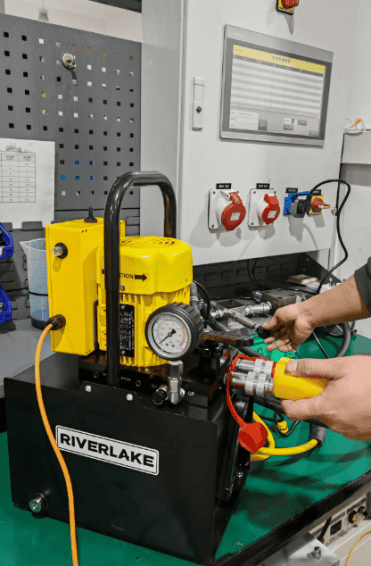
- Pressure Source
- Electric pump (indoor): 700 bar, 70 dB max
- Air-over-hydraulic (hazardous areas): ATEX-certified
Step-by-Step Operation Protocol
Pre-Operation Safety
- Install axial safety blocks (prevents projectile ejection)
- Verify puller alignment (<0.5° deviation from shaft centerline)
Extraction Process:
- Thermal Preparation (Optional):
- Heat housing to 80–120°C with induction coil (reduces force by 30%)
- Gradual Loading:
- Stage 1: 25% force → hold 2 minutes (seats jaws)
- Stage 2: 60% force → hold until movement initiates
- Stage 3: 100% force → maintain until separation
- Pressure Release:
- Engage bypass valve at 110% target pressure
Troubleshooting Field Failures
| Symptom | Root Cause | Solution |
|---|---|---|
| Slipping Jaws | Insufficient grip surface | Use V-groove inserts (depth ≥0.8mm) |
| Hydraulic Leak | Piston seal wear | Replace polyurethane seals (Shore 90A) |
| Stuck Component | Corrosion bonding | Inject MoS₂ penetrant (≥40% concentration) |
| Uneven Movement | Misalignment | Laser-align puller within 0.3° |
Emerging Technologies
- Smart Strain Monitoring:
- Bluetooth-enabled load cells map stress distribution in real-time
- Ceramic-Coated Jaws:
- HVOF-applied WC-Co coatings (hardness 2,200 HV) extend service life 10×
- AI Configuration Tools:
- Input shaft dimensions → auto-generate puller setup (tested at Bosch Rexroth)
Conclusion: Precision Preserves Assets
A SKF study revealed that 83% of bearing failures during removal result from improper techniques. By implementing:
- Force-calibrated hydraulic pullers
- Thermal expansion protocols
- Every 50-use recalibration
Maintenance teams reduce extraction-related damage by 90%. For mission-critical disassembly, precision pullers aren’t an expense—they’re insurance against catastrophic downtime.
“The bitterness of poor quality remains long after the sweetness of low price is forgotten.”
— Benjamin Franklin
Standards Compliance:
- DIN 14800-1:2018 (Hydraulic tool safety)
- ISO 286-2:2010 (Interference fits)
- ISO 6789-2:2017 (Torque tool calibration)