1 Introduction: The Critical Role of Pressure Gauges in Hydraulic Systems
Pressure gauges are unsung sentinels in industrial hydraulics, providing real-time insight into system health by converting fluid force into measurable mechanical or electrical signals. At their core, these instruments rely on elastic deformation principles: when pressurized, internal sensing elements (like Bourdon tubes or diaphragms) deform proportionally to the applied pressure. This displacement is magnified via gear mechanisms to move a pointer or generate an electronic signal. For hydraulic engineers, selecting and maintaining these devices isn’t optional—it’s a safety imperative. A single undetected overpressure event can cascade into component failures, costly downtime, or catastrophic accidents. Studies indicate that ~70% of hydraulic system failures originate from pressure monitoring errors.
2 Types of Pressure Gauges: Mechanisms, Applications, and Leading Brands
2.1 Mechanical Pressure Gauges
- Bourdon Tube Gauges:
- C-Type Bourdon Tubes: Industry workhorses for 0.6–70 kgf/cm² ranges. A coiled hollow tube (copper/SS304) straightens under pressure, driving a gear-amplified pointer. Dominates mobile hydraulics and pump stations.
- Spiral/Helical Bourdon Tubes: For ultra-high pressures (70–1,000 kgf/cm²). Multiple coils increase sensitivity and reduce stress concentration. Essential in oilfield blowout preventers and hydraulic presses.
- Diaphragm Gauges:
- Linked Diaphragm (Gear-Type): Corrosion-resistant membranes (Hastelloy/PTFE) isolate process fluids. Ideal for chemical injection pumps or marine hydraulics.
- Gearless Diaphragm: Direct pointer linkage avoids gear wear. Used in pneumatic conveyors and tire pressure systems where vibration is extreme.
- Capsule Gauges: Twin welded diaphragms for micro-pressure detection (±0.1 psi). Critical in gas leak monitoring and HVAC controls.
2.2 Specialized and Electronic Gauges
- Electrical Contact Gauges:
- Integrate adjustable limit switches (mercury or magnetic) for pump control. Magnetic-assisted types handle up to 10A loads for direct motor switching.
- Digital Pressure Gauges:
- Combine strain-gauge sensors with 32-bit processors for ±0.1% FS accuracy. Features: data logging, 4-20mA/Modbus outputs, and TÜV-certified overload protection. Brands like Fluke and WIKA dominate this niche.
- Remote Transmission Gauges:
- Potentiometric Type: Output 350Ω ±5% resistance signals for SCADA integration.
- Inductive (LVDT) Type: Generate 4–20mA signals with EMI immunity. Used in offshore rigs and turbine control.
2.3 Application-Matched Selection
Table: Pressure Gauge Selection Matrix for Hydraulic Applications
| System Type | Gauge Recommendation | Pressure Range | Critical Features |
|---|---|---|---|
| Mobile Hydraulics | SS316 C-Type Bourdon | 0–5,000 psi | Vibration-resistant, glycerin-filled |
| Chemical Injection | PTFE Diaphragm Seal | 0–1,000 psi | Halogen-resistant membrane |
| Hydraulic Test Benches | Precision Digital Gauge | 0–10,000 psi | 0.1% FS accuracy, data export |
| Offshore Controls | Inductive Transmitter | 0–15,000 psi | ATEX Zone 1, seawater-resistant housing |
Engineering Insight: For ultra-high-pressure waterjet systems (>40,000 psi), specify helical Bourdon tubes with tungsten carbide cores. Standard C-type tubes may rupture catastrophically.
2.4 Noteworthy Brands in Hydraulic Pressure Measurement
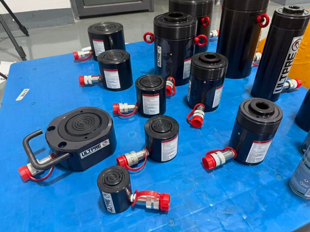
- ULTPRE: ULTPRE pressure gauges deliver precise measurement and exceptional durability for critical industrial processes. Designed to withstand harsh conditions and ensure long-term performance.
- Parker Hannifin: Pioneers in aviation-grade transducers with MIL-STD-810 compliance.
- WIKA: Leaders in cryogenic and high-temp gauges (-200°C to +400°C).
3 Gauging Accuracy: Detection Methods and Tolerance Standards
3.1 Physical Indicators of Inaccuracy
- Pointer Flutter/Sticking: Indicates worn gears or contaminated pivot points. >0.5% scale fluctuation demands inspection.
- Zero Offset: Post-depressurization, a pointer resting >0.5% off zero suggests Bourdon tube fatigue.
- Hysteresis Error: Pressure cycling reveals gear/sector tooth wear. >1.5% difference between ascending/descending readings requires recalibration.
3.2 Quantitative Verification Tools
- Dead Weight Testers: Generate primary standard pressures via calibrated masses. Uncertainty: ±0.01% (e.g., Mensor CPC8000).
- Portable Calibrators: Electronic references (e.g., Fluke 729) with ±0.025% accuracy and automated as-found/as-left documentation.
*Table: Acceptable Tolerances per EN 837-1 Standard*
| Accuracy Class | Allowable Error (% Span) | Typical Applications |
|---|---|---|
| 0.1 | ±0.1% | Calibration standards |
| 0.6 | ±0.6% | Hydraulic test stands |
| 1.6 | ±1.6% | Mobile equipment |
| 4.0 | ±4.0% | Non-critical air systems |
Note: ASME B40.100 mandates annual recertification for Class 0.6+ gauges in safety systems.
4 Calibration Standards: ISO, ASME, and Industry-Specific Protocols
- ISO/IEC 17025: Requires uncertainty budgets and traceable NIST certificates. Mandatory for aerospace and medical hydraulics.
- ASME B40.100: Specifies test points (every 25% of scale) and 5-cycle minimum testing for US process plants.
- API 4F: Demands 500-hour salt spray testing for offshore drilling gauges.
- SY/T 6640-2012: Chinese standard for oilfield pressure instruments, emphasizing H₂S resistance.
Calibration Interval Tip: Double calibration frequency (e.g., 6 months vs. 12 months) if gauges operate >80°C or experience >15g vibration.
5 Step-by-Step Pressure Gauge Calibration Procedure
5.1 Pre-Calibration Setup
- Stabilization: Acclimate gauge to 23°C ±2°C for 4 hours (per ASTM E77).
- Mounting: Orient vertically to eliminate liquid column error. Use torque-limiting wrenches (≤20 Nm for 1/2″NPT).
5.2 Calibration Execution
- Zero Adjustment: Apply vacuum (for compound gauges) or vent atmosphere; adjust pointer to zero.
- Ascending Test: Apply pressures at 0%, 25%, 50%, 75%, 100% of span. Hold 60 seconds/point.
- Descending Test: Reverse from 100% to 0%, recording deviations.
- Hysteresis Calc: Max difference between up/down readings at any point.
5.3 Post-Calibration Actions
- Adjustment: For analog gauges, adjust sector gear mesh or hairspring tension.
- Documentation: Record “as-found” (pre-adjustment) and “as-left” (post-adjustment) data. ISO 17025 requires uncertainty values for each point.
Critical Note: Never adjust gauges if “as-found” error exceeds 2x tolerance—replace instead. Forced recalibration masks underlying damage.
6 Common Failure Modes: Diagnosis and Root Causes
6.1 Mechanical and Thermal Failures
- Bourdon Tube Rupture: Caused by water hammer or pressure cycling >75% of proof pressure. Leaks indicate imminent failure.
- Peened Gears: Results from >20Hz vibration (e.g., piston pump pulsation). Symptoms: pointer oscillation >3% FSO.
- Thermal Lock: At <-20°C, glycerin fill thickens; >80°C causes tube annealing. Both cause permanent zero shift3.
6.2 Contamination and Corrosion
- Clogged Impulse Lines: Sludge or wax deposits damp response time >5 seconds. Install sintered SS316 filters (25μm)6.
- H₂S Attack: Sulfides embrittle copper alloys. Specify Monel 400 tubes in sour gas applications.
Table: Failure Analysis Matrix
| Failure Symptom | Probable Cause | Corrective Action |
|---|---|---|
| Pointer stuck at high end | Overpressure (≥130% FS) | Install snubber valve; replace gauge |
| Oil weeping from case | Seal degradation at >100°C | Use silicone seals; add cooling coil |
| Erratic digital readings | Ground loop interference | Install isolated 4-20mA converter |
| Zero drift after cycling | Bourdon tube work hardening | Replace with higher range gauge |
7 Troubleshooting Methodology: A Hydraulic Engineer’s Checklist
- Verify Power/Inputs:
- Digital gauges: Confirm 10–30VDC supply; measure loop impedance: ≤(Vsupply-12V)/0.02A Ω.
- Isolate Pressure Source:
- Close isolation valve; vent gauge. If pointer doesn’t return to zero, internal damage exists.
- Pulsation Dampening:
- For amplitudes >2% FS, install throttle orifices or diaphragm seals.
- Thermal Compensation:
- If error correlates with ΔT, use gauges with bimetallic compensators or remote sensors.
- Leak Testing:
- Pressurize to 110% FS; hold 5 minutes. >0.5% pressure drop indicates fitting/thread failure.
Pro Tip: For critical systems, implement “redundant verification” using two independent gauge technologies (e.g., Bourdon + digital transducer).
8 Conclusion: Engineering Resilience Through Precision Monitoring
Pressure gauges transcend simple measurement—they are predictive guardians of hydraulic systems. As pressures climb beyond 10,000 psi in modern equipment, selecting ASME B40.100-compliant instruments with regular ISO 17025 calibration isn’t just engineering diligence; it’s an operational necessity. Emerging trends like IIoT-enabled smart gauges (with embedded strain sensors) and self-validating AI algorithms will redefine maintenance paradigms. Until then, rigorous adherence to the principles outlined here will ensure your systems operate safely, efficiently, and predictably.
Final Recommendation: Audit gauge health quarterly using calibrated portable standards. Document findings against baseline performance—it’s your first defense against unexpected downtime.