The Essential Guide to Flange Alignment Tools: Types, Uses, and Best Practices

In high-pressure piping systems, a misaligned flange isn’t just an inconvenience—it’s a catalyst for leaks, vibration-induced fatigue, catastrophic gasket failure, and safety incidents. Yet, many teams still rely on “eyeballing” or basic straightedges for alignment. This blog explores why specialized flange alignment tools are non-negotiable, the types available, and how to use them correctly to ensure integrity, safety, and compliance with standards like ASME PCC-1.

Why Specialized Flange Alignment Tools Are Critical

The Essential Guide to Flange Alignment Tools

Human vision cannot detect misalignments under 0.5mm—yet industry tolerances often demand precision within this range. Without dedicated tools:

  • Gaskets fail prematurely due to uneven compression.
  • Bolt stress escalates by up to 300%, accelerating fatigue.
  • Leak risks surge, especially in toxic/flammable service.
    Tools eliminate guesswork, ensuring flanges mate perfectly before bolt tightening begins.

Types of Flange Alignment Tools

1. Mechanical Pin-Style Tools

  • Design: Steel alignment pins/clamps + dial indicators.
  • Best for: Small-to-medium flanges (≤24″), non-critical services.
  • Pros: Rugged, low-cost, no power required.
  • Cons: Manual calculations needed; limited precision (±0.1mm).

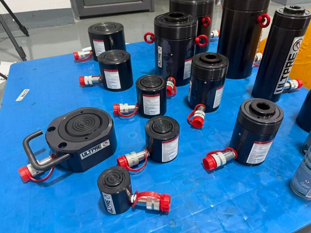
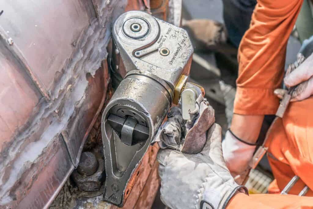
2. Hydraulic/Pneumatic Systems

  • Design: Hydraulic rams with force gauges + reaction arms.
  • Best for: Large/heavy flanges (e.g., 48″ Class 1500+).
  • Pros: Generates >100 tons of force; remote operation.
  • Cons: Requires pump/compressor; overkill for small flanges.

3. Laser Alignment Systems

  • Design: Laser emitters + receivers + digital display/software.
  • Best for: Critical applications (offshore, nuclear, pharma).
  • Pros: Micron-level accuracy (±0.01mm); real-time data logging.
  • Cons: Higher cost; training required.
    Example: Pruftechnik’s Optalign Smart exports reports for compliance audits.

4. Combination Kits

Hybrid systems (e.g., FlangeAlign) merge mechanical pins with digital sensors—balancing accuracy and affordability.

How to Use a Flange Alignment Tool: Step-by-Step

(Adapt based on tool type; this covers a standard pin-style system)

Phase 1: Safety & Preparation

  1. Isolate and depressurize the line (follow LOTO procedures).
  2. Drain residual fluid and ventilate confined spaces.
  3. Clean flange faces rigorously—debris causes 40% of alignment errors.
  4. Install 2-4 temporary studs (or alignment pins) at 3/9 o’clock positions.

Phase 2: Tool Setup

  1. Mount alignment arms/clamps symmetrically onto studs.
  2. Attach dial indicators (radial and angular).
  3. Zero all gauges with flanges loosely held.

Phase 3: Measure Misalignment

  • Radial Misalignment (Offset):
    Rotate indicators around flange circumference. Record deviations at 12, 3, 6, and 9 o’clock.
  • Angular Misalignment (Gap):
    Insert feeler gauges at 90° intervals. Max gap variance ≤0.2mm per ASME PCC-1.

Phase 4: Correct Misalignment

  1. Use hydraulic jacks or adjustment bolts to nudge flanges.
    Pro Tip: Correct angular misalignment first.
  2. Apply force gradually—avoid flange face damage.
  3. Monitor dial indicators continuously until values fall within tolerance.

Phase 5: Verification & Bolt-Up

  1. Re-check alignment after corrections.
  2. Follow cross-pattern bolt tightening (ASME PCC-1 sequence).
  3. Torque in 3 incremental passes (30%, 70%, 100%).
  4. Remove tools; perform final visual inspection.

Best Practices & Pro Tips

  • Never final-tighten bolts before alignment—rework costs 10x more.
  • For thermal lines, align at operating temperature or compensate for expansion.
  • Combine laser measurement with hydraulic tools for heavy-flange precision.
  • Train teams on all tool types—misuse voids warranties and compromises safety.

Common Mistakes to Avoid

❌ Skipping face cleaning: Even 0.05mm debris disrupts alignment.
❌ Ignoring angularity: Focusing only on radial offset causes uneven gasket crush.
❌ Over-torquing adjustment tools: Can crack flange faces.
❌ Neglecting calibration: Gauges drift—recalibrate quarterly.

Selecting the Right Tool

ScenarioRecommended Tool
Small flanges, low budgetMechanical pin-style
>24″ flanges, high forceHydraulic system
API/ASME compliance tracingLaser alignment
Mixed applicationsCombination kit

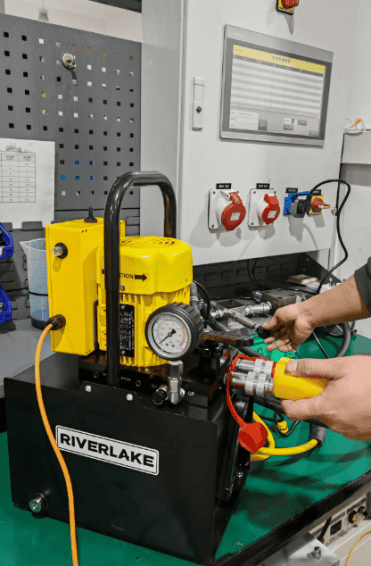
Top Brands: RIVERLAKE (hydraulic), Fluke (laser), Nord-Lock (mechanical).

Conclusion

Flange alignment isn’t a “nice-to-have”—it’s the bedrock of leak-free, safe, and efficient piping systems. Investing in the right tool reduces downtime by up to 30% and extends gasket life by 2–3x. Whether you choose mechanical pins or laser-guided systems, precision alignment pays for itself in safety, compliance, and operational continuity.

Bao Shulong

Bao Shulong is a visionary hydraulic engineer with 13+ years of specialized expertise in high-pressure fluid power systems. A 2011 graduate of East China University of Science and Technology (Mechanical Design, Manufacturing and Automation), Bao launched his career at ENERPAC’s US global headquarters, where he spent five years leading cutting-edge hydraulic tool R&D for international markets.

In 2017, he founded his own hydraulic manufacturing enterprise to redefine industry standards. Within one year of intensive R&D, his company disrupted the market with 70-300MPa high-pressure pumps that set new benchmarks for performance, durability, and value. Under his technical leadership, the venture has achieved:

300%+ growth since inception

5,000㎡ advanced manufacturing facility

¥50M annual output (2024)

37-engineer specialist team

Today, Bao’s factory produces an expanding portfolio of industrial hydraulic solutions including synchronized lifting systems, ultra-high-pressure cylinders, hydraulic torque tools, and intelligent fluid control valves – serving infrastructure, energy, and heavy industries worldwide. His engineering philosophy blends American precision standards with Chinese manufacturing innovation to deliver “no-compromise” reliability.

Related Posts

The Ultimate Guide to Tank Jacking: Principles, Procedures, and Best Practices

Introduction: Why Tank Jacking Matters Imagine a 50-meter diameter, 5,000-ton crude oil storage tank, full of product, that requires critical repairs to its deteriorating foundation. The traditional approach—emptying, dismantling, and rebuilding—is a monumentally expensive, time-consuming, and disruptive nightmare. This is where the engineering marvel of Tank Jacking comes in. Tank jacking is a highly specialized engineering technique…

Learn More
hydraulic cylinders with Gas Nitriding surface

Gas Nitriding: A Comprehensive Guide to the Surface Hardening Process

1 Introduction to Gas Nitriding Gas nitriding is a thermochemical surface treatment process that introduces nitrogen atoms into the surface of ferrous materials to enhance their surface properties. This process, developed in the early 20th century and widely adopted industrially since the 1920s, represents one of the most significant advancements in metallurgical engineering . Unlike many other heat treatment…

Learn More

The Hydraulic Torque Wrench Guide

As hydraulic engineers, we routinely encounter joints demanding immense, precisely controlled torque. Standard tools fall short here. and the hydraulic torque wrench plays an important role as the cornerstone of safety and accuracy in high-torque bolting applications across our industry. This blog delves into the technical essence, application spectrum, variations, leading brands, operational protocols, and troubleshooting of…

Learn More
Transformer Relocation

Precision Transformer Relocation Procedure: A Technical Protocol for Critical Infrastructure

1. Pre-Relocation Engineering Assessment Risk Analysis & Planning Documentation Requirements DocumentPurposeStandard ReferenceTransformer Disassembly LogRecord terminal connections, bushing torquesIEEE C57.152Lifting Force Distribution PlanSpecify jack positions and pressure settingsASME BTH-1Transport Risk MatrixIdentify vibration/shock thresholdsISO 13355:2016 2. Decommissioning & Disassembly Protocol Safe Power-Down Sequence Critical Disassembly Steps 3. Lifting & Rigging Engineering Hydraulic Lifting System Configuration Lifting Force…

Learn More

The Engineer’s Guide to Precast vs. Cast-in-Place Concrete in Modern Infrastructure

For modern construction company, the choice between precast concrete and cast-in-place (CIP) concrete directly impacts the performance of buildings being made. Both methods serve critical roles in infrastructure, yet their differences in production, installation, and longevity dictate their suitability for specific projects. What is Precast Concrete? Precast concrete (PC) refers to standardized concrete elements manufactured off-site in controlled factory conditions…

Learn More

The Hydraulic Pump: Principles, Types, and Proactive Maintenance for System Reliability

Introduction: The Heart of Hydraulic Systems In industrial machinery, construction equipment, and aerospace systems, hydraulic pumps serve as the undisputed "heart" of power transmission. These critical components convert mechanical energy from engines or motors into hydraulic energy (fluid flow + pressure), enabling precise control of force and motion. Failure risks are severe: A degraded pump in a 20-MPa excavator…

Learn More