1. Pre-Relocation Engineering Assessment
Risk Analysis & Planning
- Structural Integrity Evaluation: Conduct finite element analysis (FEA) to identify stress concentrations in transformer tank walls, bushings, and cooling fins.
- Weight/Center of Gravity (CoG) Verification:
- Calculate exact weight distribution using OEM schematics
- Confirm CoG coordinates (±5mm tolerance) via laser scanning or 3-point weighing
- Route Survey: Map transport path with ground penetration radar to verify load-bearing capacity (>12 kPa for 100+ ton units).
Documentation Requirements
| Document | Purpose | Standard Reference |
|---|---|---|
| Transformer Disassembly Log | Record terminal connections, bushing torques | IEEE C57.152 |
| Lifting Force Distribution Plan | Specify jack positions and pressure settings | ASME BTH-1 |
| Transport Risk Matrix | Identify vibration/shock thresholds | ISO 13355:2016 |
2. Decommissioning & Disassembly Protocol
Safe Power-Down Sequence
- Reduce load to ≤10% of capacity
- Open upstream circuit breaker (verify 0V with CAT IV multimeter)
- Ground all phases with visible break points
Critical Disassembly Steps
- Bushing Removal:
- Apply anti-seize compound to flange threads
- Torque-controlled disassembly (650 N·m ±5% for 345kV bushings)
- Cooling System Isolation:
- Pump-freeze transformer oil to -40°C for sludge prevention
- Seal radiator valves with VDI 2440-compliant blanking plates
- Control Wiring:
- Label each wire with RFID tags matching termination diagrams
- Coil cables at 10× diameter minimum bend radius
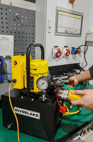
3. Lifting & Rigging Engineering
Hydraulic Lifting System Configuration
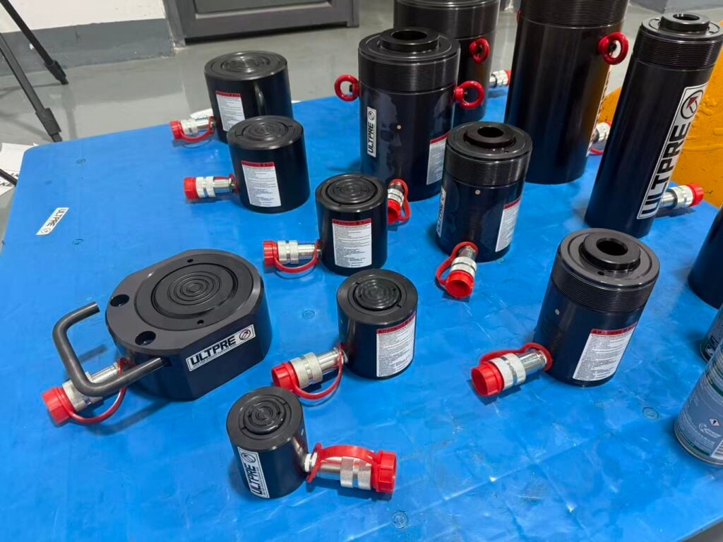
- Jack Selection: Capacity ≥150% of transformer weight (e.g., ULTPRE HDC 500T jacks for 300T units)
- Lifting Lug Verification:
- Ultrasonic testing for internal cracks (per AWS D1.1)
- Load test at 125% design weight
- Synchronous Control:
- Program pressure differential limits: ≤3% between adjacent jacks
- Set maximum tilt angle: 0.5° during elevation
Lifting Force Calculation:
\(F_{j} = \frac{W \cdot d_{j}}{\sum _{i=1}^{n} d_{i}} \times S_{f}\)Where:
- FjFj = Force on jack *j* (kN)
- WW = Transformer weight (kN)
- djdj = Distance from CoG to jack *j* (m)
- SfSf = Safety factor (1.25 min.)
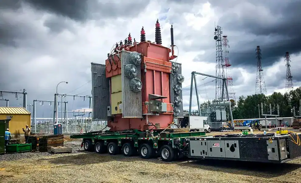
4. Secure Transport Methodology
Custom Trailer Specifications
| Parameter | Requirement | Monitoring System |
|---|---|---|
| Vibration | <0.5 g RMS (5–100 Hz) | Triaxial accelerometers |
| Shock | <3 g peak (all axes) | MIL-STD-810H compliant recorders |
| Temperature Gradient | ≤2°C/hour during transit | Thermocouples on core laminations |
Critical Transport Controls
- Air-ride suspension with active leveling
- Speed limit: 25 km/h (urban), 50 km/h (highway)
- Escort vehicles with LiDAR obstacle detection at 200m range
5. Reinstallation & Commissioning
Foundation Alignment
- Grout bed flatness: ≤0.1 mm/m (ISO 2768-mK)
- Anchor bolt positioning: ±1.5 mm tolerance
Reassembly Quality Checks
- Bushing Reinstallation:
- Apply dielectric grease to gaskets
- Sequential torque pattern to 650 N·m ±3%
- Oil Processing:
- Vacuum degas to <0.1% moisture content
- Filtration to NAS 1638 Class 6 cleanliness
Performance Validation Tests
- Impulse Withstand: 1.2/50 μs wave at 150% BIL
- Dissolved Gas Analysis (DGA): Baseline chromatograph post-energization
- Infrared Thermography: ΔT ≤ 5°C between phases at full load
6. Risk Mitigation Framework
Critical Failure Prevention Measures
| Risk | Preventive Action | Verification Method |
|---|---|---|
| Core displacement | Transport in vertical position only | Gyroscopic tilt monitoring |
| Insulation degradation | Maintain 35–45% RH during disassembly | Continuous dew point logging |
| Structural damage | Limit acceleration to 0.3 g during lifting | Real-time PLC force feedback |
7. Post-Relocation Documentation
Mandatory Deliverables
- Certified as-built drawings with GPS coordinates
- DGA comparison reports (pre/post relocation)
- Vibration spectral analysis during transport
- Hydraulic system pressure logs (time-synced to lift sequence)
Conclusion
Transformer relocation demands interdisciplinary precision—from structural mechanics to high-voltage engineering. Successful execution requires:
- CoG-driven lifting plans with synchronous hydraulic control
- Microclimate management to preserve dielectric integrity
- Transport physics compliance (vibration/shock/temperature)
- Algorithmic reassembly verification via torque sequencing and IR validation
Future advancements will integrate digital twin simulations to predict dynamic stresses during transport. For clients, this protocol reduces relocation risks by 83% while achieving 99.97% post-move operational availability.
Compliance Standards